









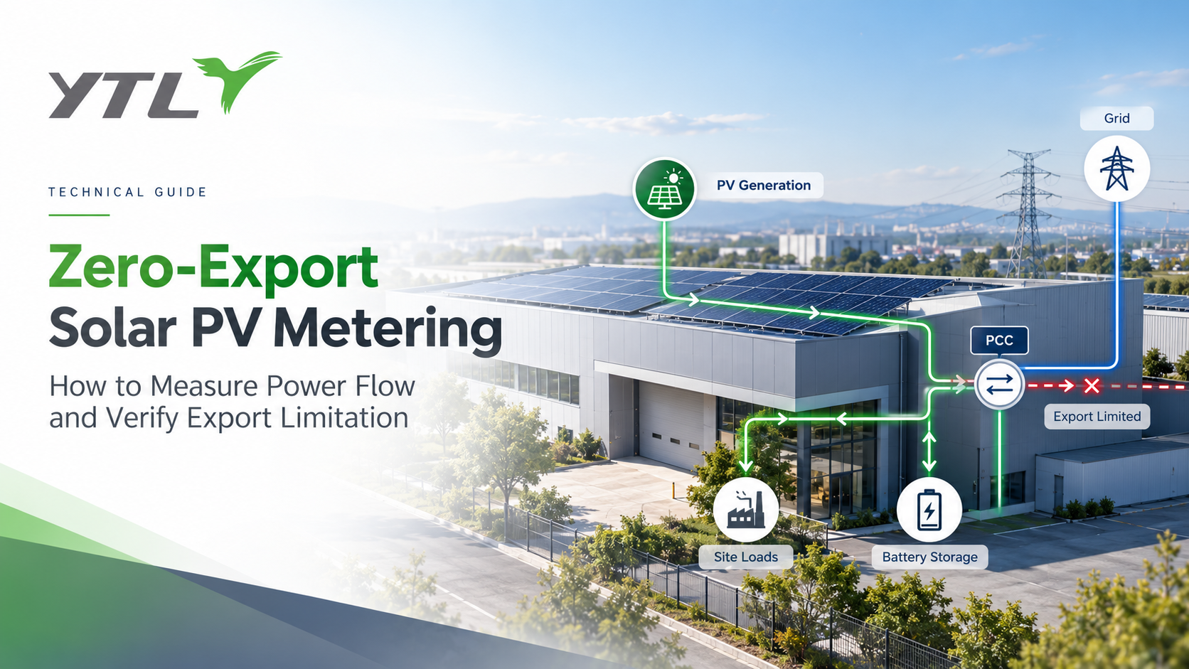
Introduction: Why Power-Flow Measurement Matters in Solar PV Projects
As commercial and industrial (C&I) solar installations expand, managing electricity exported to the distribution grid has become an important engineering requirement.
Some solar PV projects operate under zero-export or limited-export conditions. In these installations, the inverter or energy management system (EMS) must adjust power output according to the electricity flowing between the site and the grid.
Accurate power-flow measurement is therefore essential.
However, selecting a zero-export solar meter is not simply about choosing an energy meter with bidirectional measurement.
Project engineers must consider the measurement boundary, current sensor, communication interface, data refresh performance and complete control-system response.
A zero-export energy meter provides power magnitude and direction data, while the inverter or EMS is responsible for executing export limitation.
Understanding this difference helps solar EPC contractors, inverter manufacturers and system integrators select appropriate metering devices and establish reliable commissioning procedures.
1. What Is Zero-Export Solar PV Metering?
Zero-export solar PV metering refers to measuring electrical power at a defined grid connection boundary to support a system intended to prevent or limit electricity export.
In a typical C&I solar installation, the electrical system may include:
- Solar PV inverters
- Building or industrial loads
- Battery energy storage
- Distribution panels
- A grid connection
- An inverter controller or EMS
When solar generation exceeds local demand, surplus energy may flow toward the utility grid.
If the project operates under a zero-export requirement, the controller must reduce or otherwise manage the exported power according to the approved control strategy.
For example, consider a simplified installation producing 200 kW of solar power while the site consumes 150 kW.
Without additional charging loads or export limitation, approximately 50 kW could flow toward the grid, ignoring electrical losses.
A power meter installed at the appropriate grid boundary can detect the direction and magnitude of this flow.
The inverter or EMS then uses the information to adjust generation or other controllable assets.
Zero export and export limitation are not necessarily identical. Zero-export projects target no sustained export under their defined acceptance conditions, while limited-export projects may permit a specified maximum export power.
The applicable limit, tolerance and verification procedure must follow the grid connection agreement and local requirements.
2. Where Should the Zero-Export Meter Be Installed?
One of the most important design decisions is the measurement location.
For a typical grid-connected C&I solar project, the relevant monitoring point is often near the point of common coupling (PCC), where the site connects to the utility distribution network.
The meter should measure the combined effect of onsite generation, consumption and storage at the boundary relevant to the export requirement.
A simplified arrangement is:
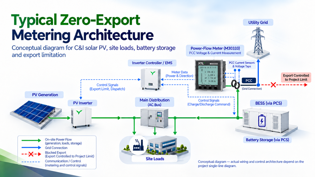
This is a conceptual diagram rather than a complete electrical wiring design.
In practice, the PCC, contractual delivery point, revenue-meter location and inverter measurement point may not be identical.
Meter placement should therefore be confirmed against the project’s single-line diagram.
For projects with multiple inverters, transformers or battery systems, additional measurement points may be necessary.
A meter installed only at the PV inverter output cannot necessarily determine total site export because it does not independently account for all onsite loads and other energy sources.
Similarly, a grid-boundary meter shows the site’s net power exchange but does not identify the individual contribution of PV and BESS without additional measurements or an approved calculation method.
For more information on different measurement locations, see YTL’s Solar PV & ESS Metering application guide.
3. CT vs Rogowski Coil: Choosing the Right Current Sensor
Current measurement is a key consideration when selecting a solar export-monitoring meter.
Two common approaches are conventional current transformers (CTs) and Rogowski coils.
Conventional CT Measurement
CT-operated meters may be appropriate when the electrical current range, required accuracy and installation conditions match the selected transformer and meter.
For example, YTL’s M60315 uses external split-core CT measurement for applications up to 100 A.
It provides a compact 18 mm DIN-rail option for selected lower-current power-flow monitoring applications.
Rogowski Coil Measurement
Rogowski coils are flexible current sensors used in compatible AC measurement systems.
They can be useful for retrofit installations and higher-current distribution circuits where installation space is limited.
YTL’s M60313-9194 supports external split-core Rogowski coil configurations for high-current measurement applications.
When choosing between CT and Rogowski coil solutions, project engineers should evaluate:
- Normal and maximum operating current
- Low-current measurement performance
- Sensor dimensions and installation space
- Conductor accessibility
- Sensor polarity and orientation
- Meter-to-sensor compatibility
- Wiring and environmental requirements
- Required measurement accuracy
Neither sensing method is universally preferable.
Rogowski coils are intended for compatible AC current measurements and should not be assumed suitable for measuring DC current.
The selected sensor and meter must be evaluated as a matched measurement arrangement.
4. How Meter Data Supports Inverter and EMS Export Control
A zero-export control architecture typically involves several separate functions.
| Component | Primary responsibility |
|---|---|
| Energy meter | Measures electrical power, energy and power-flow direction at the installed boundary |
| Current sensor | Provides the electrical input for the compatible meter |
| Gateway or communication interface | Transfers measurement data according to the system architecture |
| Inverter controller or EMS | Processes measurements and determines required control actions |
| PV inverter or PCS | Adjusts electrical output according to supported commands |
| Monitoring platform | Records operating data, alarms and performance information |
A standard energy meter does not independently determine the correct inverter output.
For export limitation, the controller must interpret the measurement data using the correct sign convention and project-specific logic.
For example, the system must consistently define whether positive active power means grid import or grid export.
Incorrect polarity, phase wiring, register interpretation or scaling can cause the controller to respond incorrectly.
Engineers should also confirm:
- The active-power register used for control
- Measurement units and scaling
- Import/export sign convention
- Data update and polling requirements
- Communication interruption handling
- Controller fail-safe strategy
- Inverter response behaviour
Reliable export limitation requires the complete measurement and control chain—not only a meter capable of detecting reverse power flow.
5. Why Fast Data Refresh Matters
Solar generation and onsite loads can change quickly.
For example, a factory may suddenly stop a production machine while its PV system continues generating power.
The reduction in onsite demand may create temporary surplus power until the export-control system responds.
This is why timely power measurements can be important.
However, several timing parameters must be distinguished:
| Parameter | Meaning |
|---|---|
| Meter measurement update | How frequently the meter updates the relevant electrical value |
| Communication response or refresh | Meter-side communication timing under specified conditions |
| Gateway polling | How frequently the gateway requests data |
| Communication latency | Time required to transfer information |
| Controller processing | Time required to interpret data and calculate a control action |
| Inverter response | Time required for the inverter to act on the command |
A short meter communication response time does not automatically guarantee an equally short system response.
The complete control loop must be tested under the project’s intended operating conditions.
YTL M60313-9194: Fast Power-Direction Data
The M60313-9194 is a compact, three-phase energy meter designed for selected anti-reverse-flow monitoring applications.
Its published product features include:
- External Rogowski coil current measurement
- High-current configurations extending to 2400 A
- Compact 18 mm DIN-rail mounting
- Specified communication refresh time of ≤50 ms
- RS485 with Modbus RTU
- WiFi/Bluetooth communication options
- Import/export energy measurement
These characteristics make the M60313-9194 an option for evaluating power-flow measurement in commercial solar PV installations.
The ≤50 ms specification is a meter-side communication performance characteristic, not a guarantee of total inverter or EMS control-loop response.
Explore the M60313-9194 Energy Meter.
6. Three-Phase Monitoring and Communication with M60333
Some projects require broader three-phase energy measurement and communication capabilities in addition to power-flow direction data.
YTL’s M60333 is a three-phase DIN-rail energy meter with external Rogowski coil measurement.
Its published features include:
- Three-phase electrical measurement
- External Rogowski coil input
- Selected configurations up to 2400 A, subject to coil and model confirmation
- RS485 communication
- Modbus RTU and DL/T 645-2007 protocols
- Specified RS485 communication refresh time of ≤75 ms
- Import/export energy measurement
- Time-of-use energy metering
- Electrical parameter monitoring and alarms
These functions can support selected PV, BESS and industrial energy monitoring applications where a gateway, controller or EMS requires three-phase measurement data.
For system integrators, it is important to verify the exact register map, current sensor configuration and communication timing before connecting the meter to a third-party platform.
The M60333 provides measurement and communication functions. The required zero-export control strategy and system acceptance remain project-level responsibilities.
7. Additional Power Monitoring and Harmonic Analysis with M30333
Not every solar project needs only active-power direction measurements.
Industrial solar installations may also require more detailed electrical monitoring at distribution panels, inverter AC circuits or other defined measurement points.
This is particularly relevant when engineers need information about voltage, current, power factor, imbalance or harmonic conditions.
YTL’s M30333 is a 96 × 96 mm multifunction panel power meter using external Rogowski coil measurement.
Its published capabilities include:
- Three-phase voltage, current, power and energy measurement
- External Rogowski coil current sensing
- 2nd–63rd voltage harmonic analysis
- 2nd–63rd current harmonic analysis
- RS485 and Y-Bus communication
- Digital input and output functions
- Event alarms and sequence-of-events recording
- Panel-mounted installation for electrical distribution monitoring
In solar PV and energy storage projects, harmonic measurements can help engineers observe electrical conditions at selected AC measurement points.
For example, a project may need to investigate harmonic content on the AC side of a PV inverter or battery power conversion system.
However, a multifunction power meter does not automatically replace a dedicated power-quality analyser, disturbance recorder or equipment used for formal harmonic compliance testing.
The M30333 is particularly relevant when the project requires more detailed electrical monitoring alongside its energy measurement architecture.
It should not be selected solely on the assumption that all zero-export monitoring meters provide the same harmonic functions or communication response performance.
8. Commissioning and Verification: Can the System Actually Limit Export?
Meter selection alone cannot verify that a zero-export system will perform correctly.
Site commissioning should include measurement checks, controller checks and dynamic operating tests.

Measurement Verification
Confirm that:
- The meter is installed at the intended electrical boundary.
- Voltage and current wiring match the system configuration.
- CT or Rogowski coil polarity and orientation are correct.
- Phase mapping and sequence are correct.
- Import and export values use the agreed sign convention.
- The displayed and communicated values are consistent with reference measurements.
Communication Verification
Confirm that:
- The controller reads the correct registers.
- Units, scaling and data types are interpreted correctly.
- Polling and update behaviour meet the agreed requirements.
- Communication interruptions are detected.
- Data quality and missing readings are handled according to the control design.
Dynamic Operating Tests
Where permitted by the project test plan, verification may include:
- A rapid decrease in site load
- A change in PV output
- BESS charging or discharging transitions
- Multiple inverter operating conditions
- Temporary communication interruption
- Recovery after communication restoration
The project should record the relevant power measurements, controller commands and inverter responses using appropriately time-aligned data.
Acceptance must be assessed against the permitted export limit, response requirements, tolerance and safety provisions defined by the project.
Normal interval energy readings may not capture every short-duration excursion. Additional test instrumentation may therefore be necessary when the acceptance procedure requires higher time resolution.
9. Zero-Export Solar Metering Buyer Checklist
Before selecting a meter, solar EPC contractors and system integrators should confirm the following.
| Review item | What to confirm |
|---|---|
| Application | Zero export, limited export or general power-flow monitoring |
| Measurement boundary | PCC or other project-defined boundary |
| Electrical system | Three-phase wiring, voltage and frequency |
| Current range | Normal, minimum and maximum operating current |
| Sensor | CT or Rogowski coil, including matched configuration |
| Power direction | Import/export sign convention |
| Control data | Required active-power registers and scaling |
| Communication | RS485, Modbus or another supported interface |
| Timing | Meter refresh, polling and overall system response |
| Fail-safe behaviour | Controller action when measurements are unavailable |
| Additional monitoring | Energy, voltage, current, PF, alarms or harmonics |
| Data origin | Measured, estimated or substituted |
| Data availability | Available or missing |
| Validation status | Unvalidated, validated or rejected |
| Processing status | Raw or corrected |
| Certification | Applicable model-specific requirements |
| Commissioning | Polarity, direction, communication and dynamic tests |
The final meter configuration should be reviewed together with the inverter or EMS supplier.
10. How YTL Supports Zero-Export Meter Selection
Zhejiang Yongtailong Electronic Co., Ltd. (YTL) manufactures energy metering and power measurement products for selected commercial, industrial, solar PV, battery storage and power-distribution applications.
For zero-export and power-flow monitoring projects, YTL can support initial evaluation of several meter options.
| YTL model | Main selection consideration |
|---|---|
| M60313-9194 | Compact, fast power-direction measurement with external Rogowski coil |
| M60333 | Three-phase DIN-rail measurement, RS485 integration and energy monitoring |
| M30333 | Multifunction panel monitoring with detailed harmonic analysis |
| M60315 | Alternative split-core CT arrangement for selected lower-current applications |
The three principal models address different project requirements rather than serving as identical replacements.
YTL can assist with initial model selection, electrical range review, current-sensing arrangement, communication requirements, register-map discussion and sample-level meter-to-gateway evaluation.
Actual compatibility, refresh characteristics, accuracy, certification status and available functions must be verified against the selected model, firmware and project architecture.
YTL supports the field-level electrical-measurement and data-output layer.
Inverter control, EMS optimisation, export-limitation algorithms, grid-code compliance and final system acceptance remain the responsibility of the relevant project, equipment and engineering parties.
Explore the complete Meters for Zero-Export Control product category.
11. Frequently Asked Questions
What is a zero-export solar meter?
A zero-export solar meter measures electrical power and its direction at a defined boundary, providing information that an inverter or EMS can use for export limitation.
Can an energy meter prevent solar power from flowing into the grid?
Not by itself. The meter measures the relevant electrical quantities, while the controller or inverter performs the required control action. Complete system performance requires commissioning and verification.
Where should a zero-export meter be installed?
The measurement point is commonly near the PCC, but its exact location depends on the electrical architecture and contractual export boundary. The project’s single-line diagram should be reviewed before installation.
Is a Rogowski coil better than a conventional CT for solar export monitoring?
Not necessarily. Rogowski coils may suit higher-current installations and constrained mounting arrangements, while conventional CTs may be suitable for other current ranges and measurement requirements. Sensor selection must account for accuracy, installation and meter compatibility.
Does a 50 ms meter communication refresh guarantee zero export?
No. Meter-side communication timing is only one part of the overall control-loop response. Controller processing, network latency, inverter behaviour and fail-safe logic must also be considered.
Can a zero-export meter measure harmonics?
Some multifunction meters support harmonic monitoring, but not every zero-export meter does. For example, YTL’s M30333 supports 2nd–63rd voltage and current harmonic analysis. The exact monitoring requirements should be matched to the meter specifications.
Can YTL meters be integrated with an inverter or EMS?
Selected YTL meters provide communication interfaces such as RS485 and Modbus RTU. Integration requires confirmation of the selected meter, register map, controller interface, communication timing and project-specific compatibility.
For more technical questions, visit YTL’s Frequently Asked Questions page.
Conclusion
Zero-export solar PV metering is not simply a matter of detecting reverse energy.
Successful power-flow monitoring requires the correct measurement boundary, compatible current sensing, reliable communication and a properly designed controller or inverter response.
For commercial and industrial solar projects, choosing between CT and Rogowski coil measurement, fast power-direction monitoring and multifunction electrical analysis should depend on the actual project requirements.
YTL offers different measurement options through its M60313-9194, M60333 and M30333 product families, with M60315 available for selected CT-based applications.
The energy meter provides measurement data. Reliable export limitation depends on how the complete system uses that data.
Discuss Your Zero-Export Solar Metering Requirements
Are you developing a commercial solar PV project, integrating an inverter controller or selecting meters for a power-distribution cabinet?
Contact YTL with your electrical single-line diagram, voltage and current requirements, preferred sensor type, communication interface and control-system specifications.
Our team can help you evaluate a suitable meter configuration and discuss the next steps for sample testing and integration.
