English
 简体中文
简体中文
1、 Comparison of Core Principles and Structures
1. Current Transformer (CT)
Working principle: Based on the principle of electromagnetic induction, the large current on the primary side is converted into a small current on the secondary side by closing the iron core and winding. The transformation ratio (K) is determined by the turns ratio of the primary winding to the secondary winding, and in typical applications, the secondary side current is 5A or 1A.
Structural features:
Including iron core and winding, the secondary side must strictly avoid open circuit (otherwise high voltage will be generated due to magnetic saturation).
The output is a current signal, which needs to be converted into a voltage signal through a resistor for processing by the sampling chip.
2. Diverter
Working principle: Using low resistance manganese copper sheets or precision resistors, the current is calculated by measuring the voltage drop at both ends (Ohm's law, V=I × R).
Structural features:
The structure is simple, directly connected in series in the circuit, with no risk of open circuit.
The output is a voltage signal that needs to be processed by an amplification circuit before being sent to the metering chip.
Manganese copper material has a low temperature coefficient (about 0.002%/℃) and excellent environmental adaptability.
2、 Detailed explanation of performance differences
1. Measurement range and accuracy
Current transformer:
Advantages: Suitable for high current scenarios (such as hundreds of amperes), with an accuracy typically ranging from 0.2% to 1%.
Limitations: There is a large error under low current (due to the influence of excitation current), and the linear range is narrow (mainly at 50Hz/60Hz power frequency).
Diverter:
Advantages: Higher accuracy (up to ± 0.5%) and excellent linearity at low currents (such as a few amperes).
Limitations: Power loss is significant at high currents (e.g. 100A current passing through a 0.1m Ω splitter results in a loss of up to 1W).
2. Anti interference and safety
Current transformer:
By using electromagnetic isolation to achieve high and low voltage separation, it has strong anti-interference ability and is suitable for high voltage environments (such as substations).
Open circuit on the secondary side may cause overheating or even damage to the iron core.
Diverter:
Direct sampling requires additional isolation circuits (such as differential amplifiers), which limits its application in high-voltage scenarios.
There is no risk of open circuit, but the impact of circuit voltage division on the original system needs to be considered.
3. Temperature stability
Current transformer: The iron core material (such as silicon steel sheet) is easily affected by temperature, resulting in magnetic permeability and accuracy fluctuations.
Diverter: Manganese copper material has a low temperature coefficient and better environmental adaptability.
3、 Application scenario analysis
1. Typical applications of current transformers
Three phase energy meter: In industrial electricity metering, when dealing with high currents (such as 100A or above), it is necessary to isolate the high voltage and measurement circuit.
High voltage transmission system: In substations, relay protection equipment is used to measure the current of transmission lines.
Communicating high current scenarios: such as motor control and power grid monitoring.
2. Typical Applications of Diverters
Single phase energy meter: Processing small currents (such as below 60A) in household electricity metering, pursuing high accuracy.
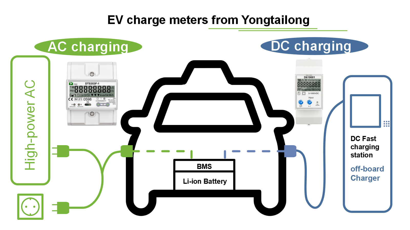
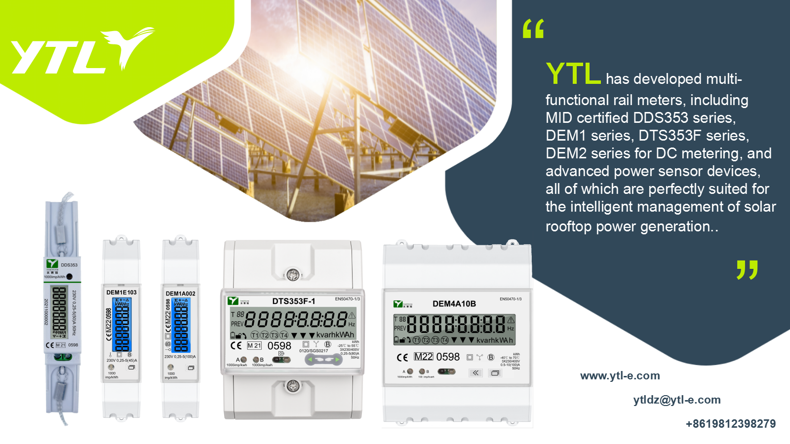
DC meters: photovoltaic power generation, electric vehicle charging stations.
Laboratory and Precision Instruments: Scenarios that require direct measurement of current and high precision.
4、 Cost and process comparison
Cost: The current transformer has a complex structure (iron core, winding) and high cost; The shunt has a simple structure (manganese copper sheet/resistor) and low cost
Process requirements: The current transformer requires precise winding and magnetic circuit design; The splitter requires high-precision machining to ensure stable resistance
Batch application: suitable for large-scale industrial scenarios (such as three-phase electricity meters); Suitable for consumer level scenarios (such as single-phase meters, three-phase meters, DC meters)
5、 Selection criteria and decision-making framework
Current magnitude:
High current (>100A) prioritizes CT, low current (<50A) prioritizes shunt.
Accuracy requirements:
High precision metering (such as 0.5S level electric energy meters) tends to use a shunt.
Environmental conditions:
High temperature or strong electromagnetic interference environments are suitable for CT, and temperature stable scenarios are suitable for splitters.
Circuit type:
AC meters can choose CT or shunt, while DC meters are only suitable for shunt.
6、 Future Development Trends
Current Transformer: Developing towards high precision and wide bandwidth (such as using Roche coils for transient current measurement).
Diverter: Material innovation (such as nanocrystalline alloys) further enhances temperature stability and integrated design reduces costs.
Hybrid solution: Develop a composite sampling module by combining the isolation advantages of CT with the high precision of shunt.
In modern smart grids, distributed energy access, and complex load environments, the demand for accurate measurement of current waveforms is increasing. Diverters, with their excellent performance (especially in harmonic and DC adaptability) and cost volume advantages, have become the dominant technology for current sampling in smart energy meters, especially in the field of small and medium-sized current measurement in residential and commercial areas. CT maintains its important position in specific scenarios with high voltage, high current, and requirements for traditional interfaces. The selection of technology ultimately serves the goal of precise, safe, reliable, and economical energy metering.


")


.png?imageView2/2/w/500/h/500/format/png/q/100 "YTL Two Phase Three Wire Big counter Electricity Meter")